


- Product Description
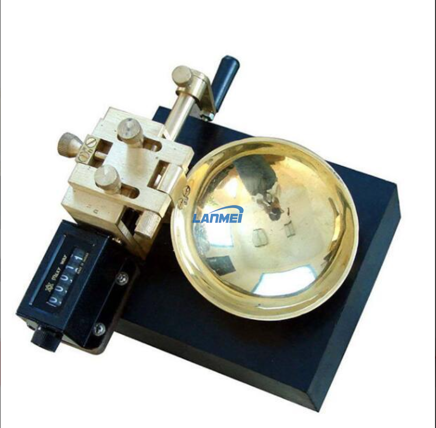
Manual Liquid Limit Device
Manual Liquid Limit Device (Casagrande) are used to determine the moisture content at which clay soils pass from plastic to liquid state. The Devices consist of an adjustable crank and cam mechanism, a blow counter and a removable brass cup fitted on the base.
The dish-type liquid limit meter is used to measure the liquid limit of soil. It is an equipment used for design and construction in order to classify soil types, calculate natural consistency and plasticity index.
Experiment procedure
1. Put the soil sample in an evaporating dish, add 15 to 20 ml of distilled water, repeatedly stir and knead it with a soil adjusting knife until it is thoroughly mixed, then add 1 to 3 ml of water each time, and mix thoroughly according to the above method. all.
2. When the soil material is mixed with sufficient water to reach a consistency, it is equivalent to need to drop 30 to 35 times to combine. Place a portion of the clay paste in the dish above where the dish touches the bottom plate. Use a soil adjusting knife to press the soil paste into a certain shape, pay attention to pressing it as few times as possible, and prevent blisters from being mixed into the soil paste. Use a soil-adjusting knife to smooth the surface of the soil paste, and the thickest part of the soil paste is 1 cm thick. The excess soil is returned to the evaporating dish, and the soil paste in the dish is slashed along the diameter with a groover from the cam follower. A well-defined, defined slot is formed. In order to prevent the groove edge from tearing or the soil paste sliding in the dish, at least six strokes from front to back and from back to front are allowed to replace one groove, and each stroke is gradually deepened until the last time. Significant contact with the bottom of the dish should be scored as few times as possible.
3. Turn the crank handle F at a speed of 2 revolutions per second to make the soil plate rise and fall until the two halves of the soil paste touch at the bottom of the groove about 1/2 inch (12.7 mm). Record the number of hits required for a 1/2 inch length of groove bottom contact.
4. Cut a soil piece perpendicular to the slot from the soil side to the side, the width of which is approximately equal to the width of the soil cutting knife, including the soil at the closed slot, put it in a suitable weighing box, weigh and combine it. Record. Bake to constant weight at 230°±9°F (110°±5°). Immediately after cooling and before sucking in the adsorbed water, weigh. Record the weight loss after drying as water weight.
5. Move the remaining soil material in the dish to the evaporating dish. Wash and dry the dish and groover, and reload the dish for the next experiment.
6. Use the soil material moved to the evaporating dish to add water to increase the fluidity of the soil, and do at least two more experiments according to the above method. The purpose is to obtain soil samples of different consistency, and the number of drops required to make the joints of the soil paste flow together is more than or less than 25 times. The number of drops obtained should be between 15 and 35 times, and the soil sample is always carried out from a dry state to a wet state in the test.
7. Calculation
a Calculate the water content WN of the soil, expressed as a percentage of the dry soil weight;
WN=(water weight×dry soil weight)×100
8. Draw the plastic flow curve
Plot the 'plastic flow curve' on semi-logarithmic paper; it represents the relationship between water content and the number of dish drops. Take the water content as the abscissa and use a mathematical scale, and use the number of falls as the ordinate and use a logarithmic scale. The plastic flow curve is a straight line, which should pass through three or more test points as far as possible.
9. Liquid limit
On the flow curve, the water content at 25 drops was taken as the liquid limit of the soil, and the value was rounded to an integer.


Hot Products

Cast Iron Cube Moulds For Laboratory
Concrete Testing Equipment for Sale

Concrete Magnetic Shaking Table

Double Shaft Two Screw Mixer Humidifier For Fly Ash Dust

Laboratory Hot Air Constant Temperature Drying Oven

Cement Vibro Shaker Sifter Sieve Vibrating Screen
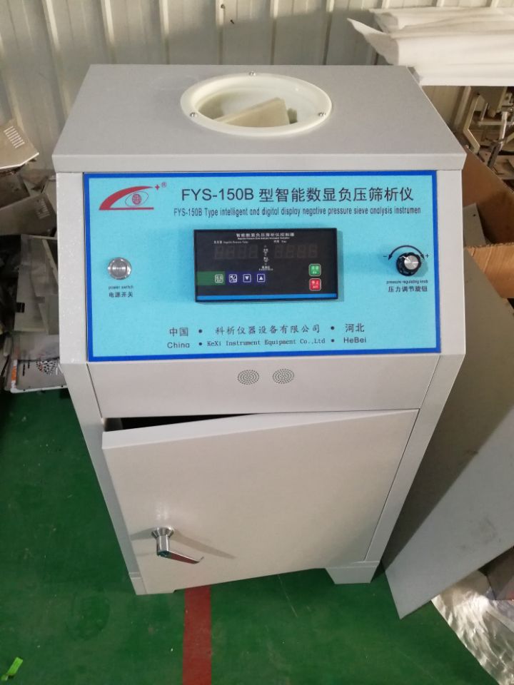
Cement Laboratory Negative Pressure Sieve Analyzer

Lab Standard Concrete Cement Curing Chamber

Laboratory Precision Biochemistry Incubator Coled Bod Refrigerated Incubator

Small Jaw Crusher
Contact us
Please feel free to give your inquiry in the form below We will reply you in 24 hours